Shastri Ram
Roboticist - Engineer - Innovator
Roboticist - Engineer - Innovator
Hi, I'm Shastri. I'm a Robotics Engineer from the amazing country of Trinidad and Tobago, in the Caribbean. After winning the nation's highest award, the President's medal in 2011, I attended Carnegie Mellon University to complete a double major in Electrical and Computer Engineering, and Robotics. I graduated in May 2016 with University Honors, and honors from Tau Beta Pi (Engineering Honor Society) and Eta Kappa Nu (Electrical and Computer Engineering Honor Society). Immediately after, I decided to pursue Masters of Science in Robotics at Carnegie Mellon University, from which I graduated in July 2018. For my MSc, I focused on deep learning and computer vision for mobile robotics applications, which culminated in my thesis entitled Semantic Segmentation for Terrain Estimation Using Data Autolabeled with a Custom Roughness Metric. Currently I am an Automation Engineer at Caterpillar Inc, where I am working towards solving challenging and interesting autonomy and perception problems in the construction and mining industry.
With a deep passion for programming, tinkering, hacking and inventing, I absolutlely love working on projects. Previous experience in Mechanical, Electrical, Software and Civil Engineering provides me with the unique ability to speak in different Engineering languages and I can contribute to many different aspects of a project. However, my specialty lies with software and perception, and I have done some of my greatest work in these areas. I'm an avid car enthusiast and I love racing. I enjoy listening to music, watching movies, cooking and being an island boy, I love the outdoors and nature!
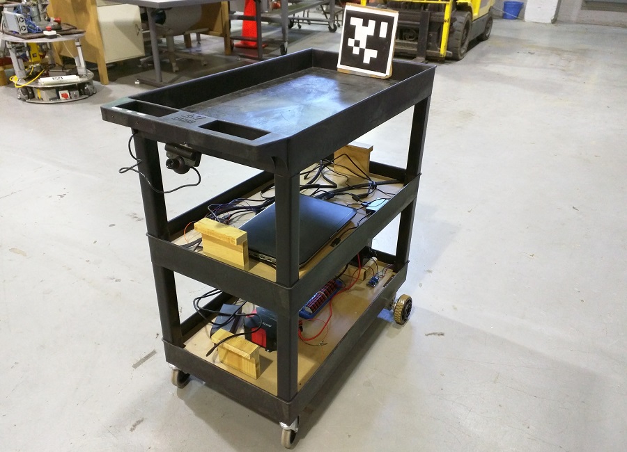
EZ-Kart is an robotic cart that is able to autonomously "follow" in front of a user. This robot was the final project for the Spring 2016 Robotics Capstone course (16-474) at Carnegie Mellon University. My most major contributions to the project were the development of the controller and the power system. EZ-Kart was built and designed with the collaboration of Clayton Ritcher and Mopewa Ogundipe. Warehouse workers' bodies face a lot of stress and fatigue from constantly pushing heavy carts around the building. EZ-Kart was designed to ease this burden.
All the processing is done on an Dell Inspiron laptop running Ubuntu 14.04 and ROS Idigo Igloo. EZ-Kart uses speech recognition to start and stop following with the words "EZ-Kart Start" and "EZ-Kart Stop" respectively.The user speaks to the robot via a bluetooth headset with feeds the audio input into a speech recognition library. The robot locates a user using the April Tag computer vision library. The user wears the April tag at chest height and the images captured from the PS Eye camera is fed into the library which returns the distance of the user from the robot, as well as the angular offset of the user from the robot.
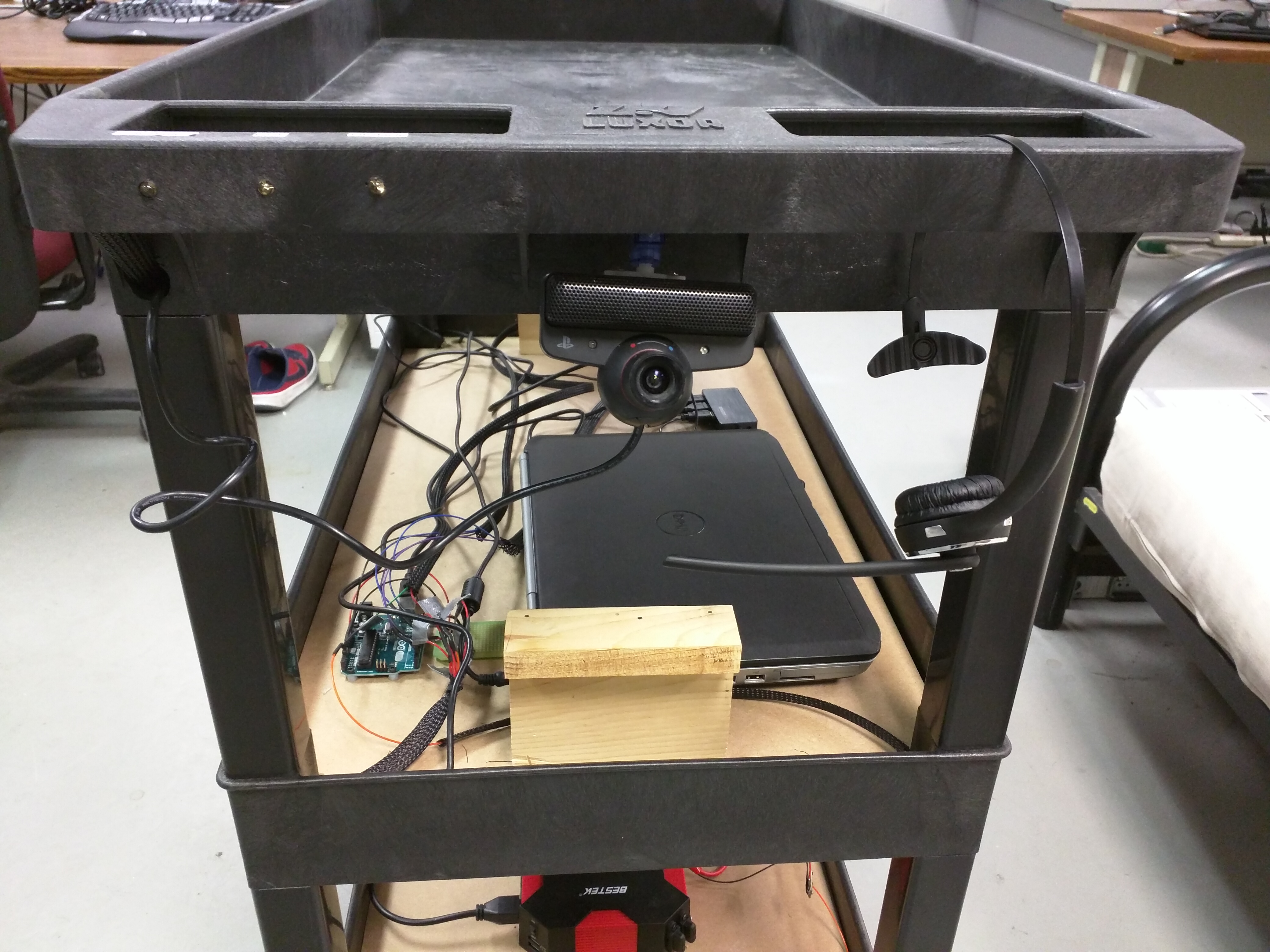
A message with the distance and angle offset is passed to the controller. The controller consists of two series PD control loops, which output the left and right motor PWM signals. The PWM signals are passed to an ROS/Arduino node which sends the PWM signals via serial to an Arduino Uno. The signal is then relayed to the motor controllers for each wheel. The motors have been limited to move at walking speed (approximately 3 mph) and were selected with a gearbox which enable the robot to easily carry 30lbs of cargo.
Additionally EZ-Kart has an ultrasonic distance sensor detects situated at the front of the robot. It alerts the controller when an object is with 2 feet of the robot and the controller responds by immediately stopping the robot. The user can then walk backwards to move the robot from the obstacle or can take manual control of the robot itself. The ability to have the robot be manually pushed in the case of an obtacle or low battery was a design criteria of the project.
The robot features a very simple but effective user interface. Three LED lights located on the hanldle illuminates to let the user know if there a low battery, an obtacle detected or if the robot has lost the user. Additionally, the robot had the ability to speak, alerting the user audibly if any of these situation arise. The entire robot is powered from a rechargeable sealed lead acid battery. A power distribution board splits the voltage along a 12V and 5V rail to power different components. Additionally, an inverter conencted to the battery, powers the laptop. The system is capable of continuous operation for 4 hours.
EZ-Kart was developed with the user in mind. The system is hands free and easy to use. It has the form factor of a traditional cart and the user virtually pushes the cart in a manner similar to pushing a traditional cart. This maintains a level of familiarity for users.
Below is the video of the demo of EZ-Kart
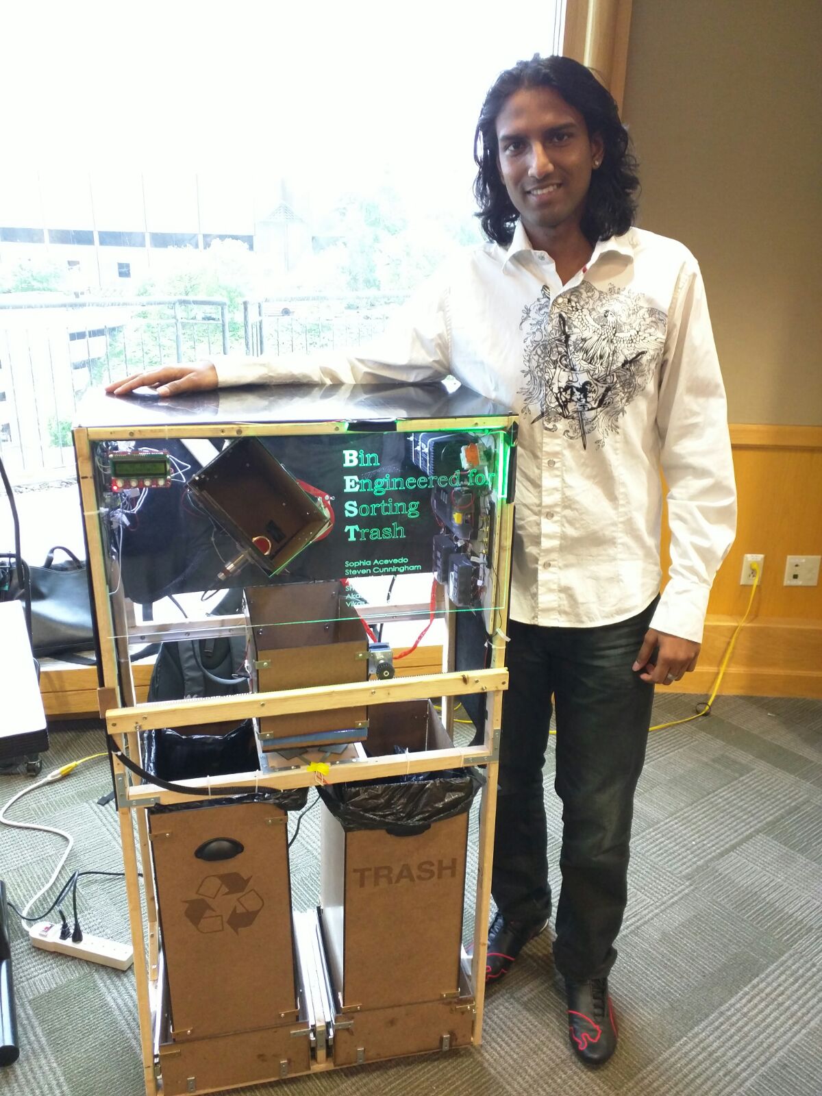
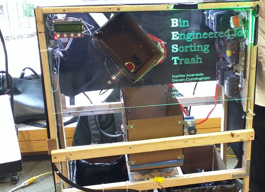
TrashBot is a trash sorting robot. It was my Electrical and Computer Engineering capstone project for Mechatronic Design (18-578). For this project, I was the principal embedded software engineer and the power/electrical system designer. TrashBot was built in collaboration with Akash Sonthalia, Vikas Sonthalia, Stephen Cunningham, Sophia Acevdo and Astha Keshan. The requirements for TrashBot were:
TrashBot uses outputs from an array of sensors to determine the type of object that needs to be sorted. A trash item is deposited into the chute at the top of the robot. The presence of an object is detected with an ultrasonice distance sensor located at the top of the chute. An inductive proximity sensor detects whether the object is metal or not. If the object is metal, it drops into the second compartment which translates to the recyclables bin. If the object is not metal, the other sensors are read. The chute contains two IR(Infrared) sensors which measure the reflectivity of IR light at a wavelength on 810nm. The chute flap opens and drops the trash item into the second compartment where the the weight of the object is detected with a load cell. All of the data from the sensors is fed into the Arduino Mega micro-controller which runs a decision tree algorithm to make a calculated guess to determine the type of trash. The box then translates left or right to deposit the trash into the approrate bin.
Ultrasonic distance sensors above the bin determine the bin fullness. The bin fullness along with the number of each type of item is displayed on the LCD screen. The front acrylic panel is displayed green when it is safe for the user to input a trash item and red when it is not. *Insert Pic of UI here*
All of the processing and classification occurs on the Arduino Mega micro-controller. The code runs the statechart pictured below. *Insert pic of statechart*
The cyberphyhsical architect is laid out as shown below. The Arduino Uno controls the UI LED Lights. A second micro-controller was needed because the control of the lights greatly slowed down the execution of the main loop in the Arduino Mega, which in turn cause the trash sorting and classification to run longer than it should. *Include pic of cyberphysical architecture*
From calculations, it was determined that the system would need a max of 5A. Additionaly some componenets needed 12V while others needed 5V. A power supply was selected that had the ability to deliver the amperage at 12V. A regulator stepped the 12V down to 5V. The power system employed the use of fuse boxes to distribute the 5V and 12V supplies. The benefits of the fuse box design included ease of wiring, ease of debugging and the ability to keep the wiring in a systematic manner. An emergency stop button and a breaker were included to protect the system from faults. The power system wiring diagram is shown below. *Include pic of power system*
TrashBot was a resounding success. My team won 1st place in the design competition, sorting 15 objects in 37 seconds with a classification ad sorting accuracy of 93%!! Enjoy our video below!
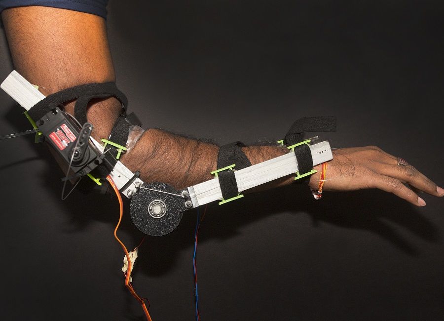
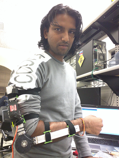
The Iron Man Arm was my entry into the Build 18 2016 Hackation. This project served as a proof of concept for strength augmentation. It was built within four days using aluminum, custom 3D printed parts, flex sensors, EMG sensors with an Arduino running custom control code. It was created in collaboraton with Johnathon Dyer, who worked on the mechanical design of the arm. I desgined the software, electronics and power system for the arm.
Creating an arm that increase the strength of the wearer would involve the use of hydraulics or pneumatics. However with only a budget of $300.00, this would not be possible. However, by showing that we could create a prosthetic that could hold the weight of the wearer's arm, it would prove that actual strength augmentation would be achievable. A high torque servo was chosen so that it could lift the weight of an average human arm.
A flex sensor placed on the elbow detects when the arm is bending. The Arduino Uno continuously reads the flex sensor and sends a control signal to move the servo depending on the amount the arm flexes. The EMG (Electromyography) sensors detected when the forearm muscle was contracted. This would illuminate the LED ring on the Iron Man glove, similar to the Iron Man suit in the movies.
After a continuous 3 hours of use, the housing for the velcro began to fatigue and fail hence the reason the exoskeleton arm slipped down my arm. However, the servo continued functioning and was able hold the weight of my arm with no effort at all.
This project was an exploration into object tracking in video. In object tracking, a template, i.e. an object is selected in a video frame and the object continues to be tracked in each subsequent video frame. I implemented the Lucas-Kanade Tracker, the Mathew-Baker Inverse Compositional Tracker with and without correction, and the Mean Shift Tracker.
The Lucas Kanade Tracker is an additive tracker. It compares the template in the current frame to the position of the template in the previous frame. It makes incremental adjustments to the parameters of a warp, which is applied to each iteration to the current frame, so that the object continues to be tracked. The result is shown in the video below. The Lucas-Kanade Additive tracker is slow since it is computationally expensive. It can also be seen that the template loses track of the vehicle as the video progresses.
The Matthew-Baker Tracker is an Inverse Compositional Tracker which means that it warps the template in the current frame and applies the inverse warp to the template in the previous frame. This is more efficient and reduces computation time. The result in the video shows that the car is tracked much better.
Mean Shift Tracking applies a statistical approach to tracking. It models the template as a distribution by applying a kernel to the pixels within the template. For each subsequent frame, the template is moved until it matches the original template as close as possible. In other words, the template is shifted till it finds the mean of the original template, hence the name Mean Shift Tracking. The results are shown below.
The Lucas Kanade Tracker works well when the object is rigid and the appearance of the object does not change much. However, to track a deformable object, this tracker would not be able to keep up. The Mean Shift Tracker handles this well and tracks regions that change in appearance quite a bit.
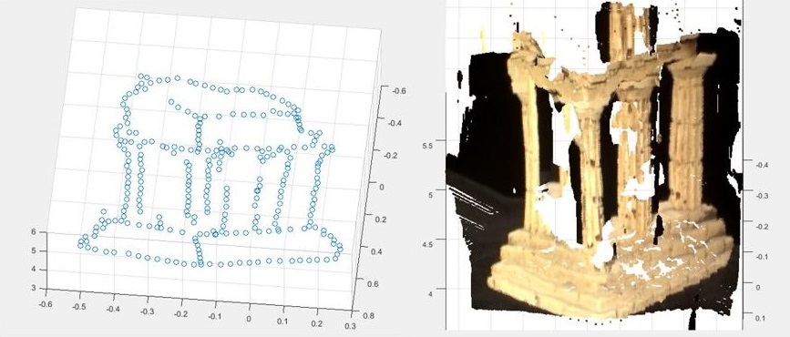
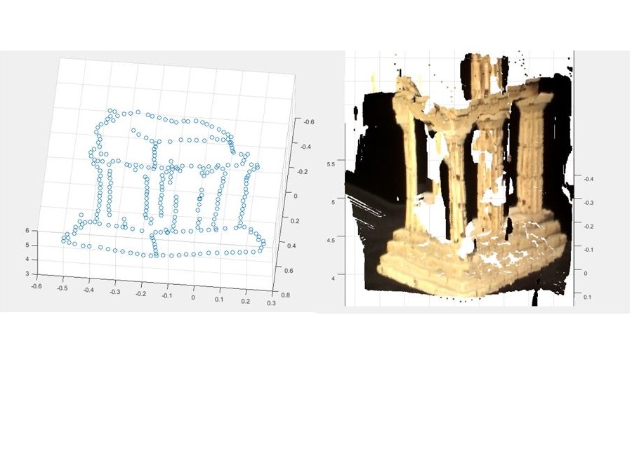
For this project, two views of a Greek temple were given, with the goal of creating a 3D reconstruction of the temple from the 2 images shown below. The code was written in MATLAB and the intrinsic or calibration matrices of the two cameras were given. First the Fundamental Matrix was calculated. The Fundamental Matrix encodes the epipolar geometry without the assumption of calibrated cameras. This was calculated using the 8-point algorithm, the 7-point algorithm and the 7-point algorithm with RANSAC. It was found that the 8-point algorithm gave the best solution. Once the Fundamental Matrix was calculated, it was straightforward to calculate the Essential Matrix, which encodes the epipolar geometry for the calibrated cameras.

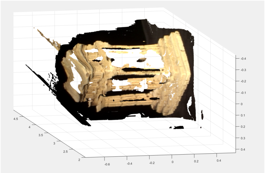
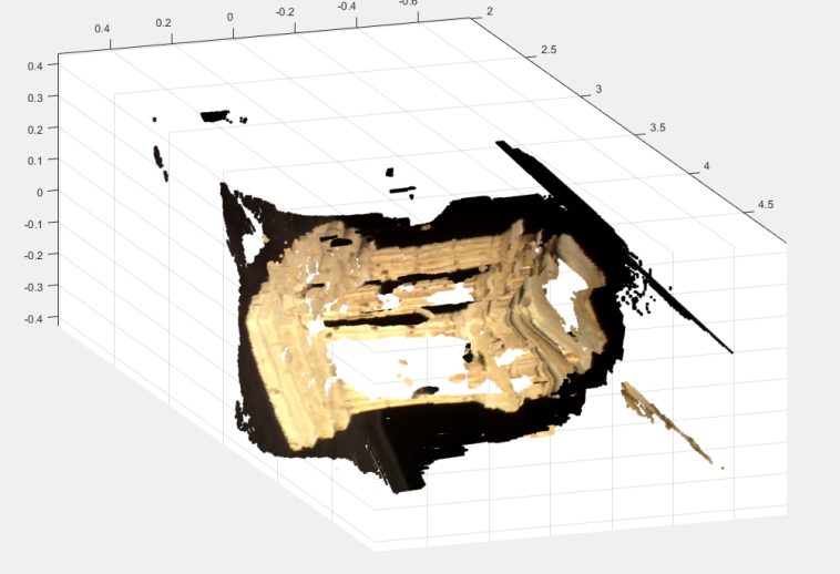
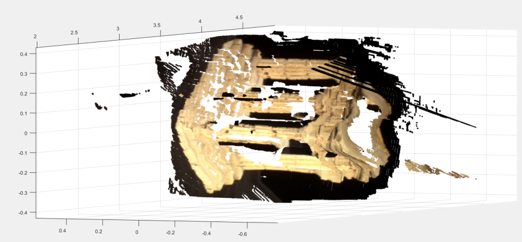
To create a 3D reconstruction, the depth of each pixel must be calculated and for this to be done, each pixel in one image must be paired with its corresponding pixel in the second image. To do this the Essential Matrix is used with each point to find the epipolar line on which the corresponding point lies. When all the point to point correspondences were found, the camera matrix for each camera was found and triangulation was done. Linear triangulation was used and the 3D image was constructed using MATLAB's pointCloud function. The results can be seen below. This was the basic method for 3D reconstruction and there can be tweaks that can be done to improve the results.
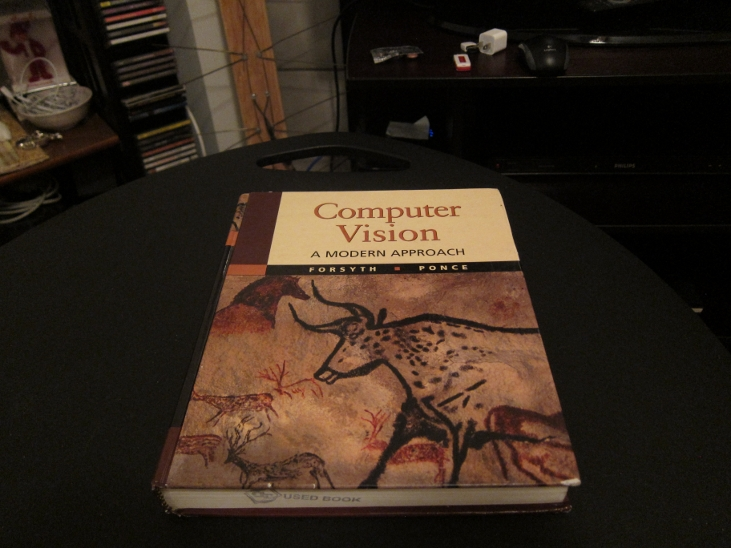
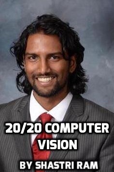
Augmented reailty superimposes one image on another image of the world, to provide a composite view. In order to do this, the transformation from the first image to the second image must be known. To illustrate this, I want to augment the image of the computer vision textbook, with the planar image of myself. Both images are shown below.
To determine the transformation needed to augment the planar image of myself onto the book cover, an planar image of the textbook was given. The FAST (Features from Accelerated Segment Test) corner point features were extracted from both images and then the FREAK (Fast Retina Keypoint) descriptor was used to extract the interest point descriptor for each corner point detected. The features were then matched by nearest distance using the sum of squared differences metric. Below you can see the matched points between the planar image of the book cover and the book on the table.

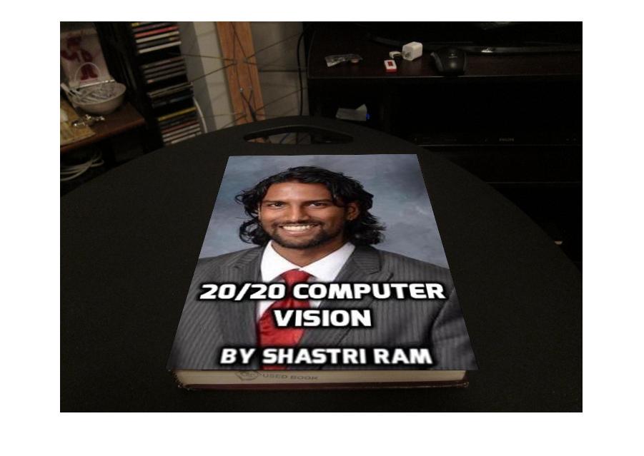
With these matching points, the homogeneous tranformation from the planar book cover to the book cover on the table was calculated. This was calculated using the RANSAC with the Direct Linear Transform with normalization. Once the tranformation was known, the image of myself was then transformed and spliced onto the cover of the book on the table. The result is shown below.
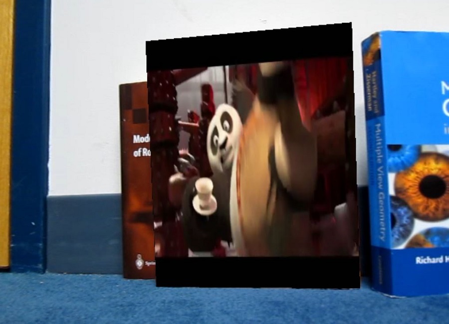
Having augmented one image with another, I turned my sights to augment one video with another. The goal was to be able to augment a Kung Fu Panda video shown below, onto the cover of the book in the second video show below.
Since a video is just simply frames of images played togeter fast, the process was similar to augmenting the previous images. The Kung Fu Panda video clip was considered to be a planar video source. Then for each video frame of the book video, the transformation was found between the planar image of the book cover to the book in the video frame. The corresponding video frame at the same timestamp in the Kung Fu Panda video clip was then transformed and spliced onto that video frame of the book. This was done for every video frame. The final result is shown below. Audio was not added.
While the result looks good, it is can be improved by using a better feature point descriptor that is rotationally invariant such as ORB (Oriented FAST and Rotated BRIEF) descriptor, and possibly more investigation into the different feature point detectors can be done. This project was done in MATLAB.
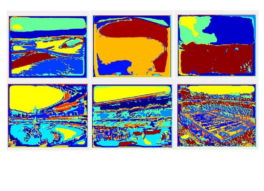
The aim of this project was to develop a system that would be able to classify an image into 8 categories: aquarium, beach, bridge, conference room, gas station, park, parking lot and waterfall. Two approaches were taken, a bag of words method using a spatial matching histogram and a support vector machine (SVM).
A bank of 38 filters (gaussian, sobel, laplacian, and gabor) were appliied to each image in the training set. Points were selected from the filter responses and clustered using K-Means to create the visual words for the dictionary. Then each image in the training set was represented using the visual words and a spatial pyramid matching histogram was used to capture semantic meaning from the image. TO classify an image in the training set, the image was represented using the visual words, its spatial pyramind matching histogram obtained and then compared to the histograms of the training set images using the histogram intersection metric as the distance measure. The prediction was then class of the test image which had the nearest distance to the training image. The accuracy of this method depended on the size of the dictionary and the number of points of each image used to create the dictionary. After testing various values of these parameters, the best accuracy obtained was 61.25%.
For the SVM method, the visual word representation of the images of the training set were used as input into the libsvm package. This gave an accuracy of 68.13%, an improvement over the previous method.
Experiemental Analysis Report of the scene classification
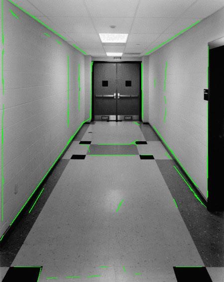
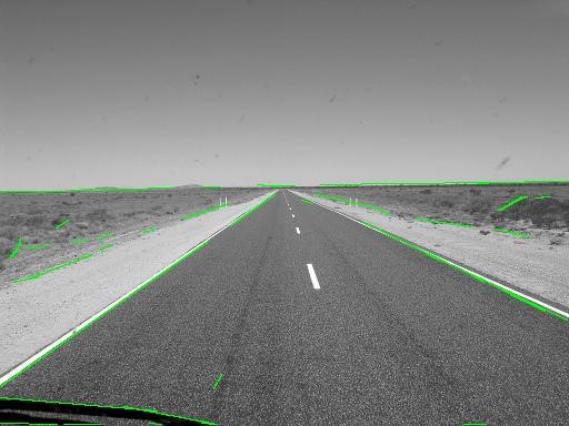
This project employed the use of image processing algorithms to create a Hough Transform based line detector, using the Matlab programming environment. For this project, Matlab's built in image processing toolbox was not used. The input image was convolved with gaussian and sobel filters to obtain the x and y derivatives of the image. Non-maximum suppression was then used to get egdes that are one pixel wide. The result of these operations would give the edges of the objects in the image. However, the goal was to extract the lines of the image. To this end, the lines were extracted using the Hough Transform method. Each edge in the image voted for the possible line that it could represent. These votes were stored in an accumulator. The accumulator then underwent non-maximum supression to determine the main lines from the image.
It must be noted that the success of the line detector depends heavily on the values of different parameters throughout the image processing pipeline. This is discussed in my final report, linked below. The final report also gives the results.
Experiemental Analysis Report of the Hough Transform Line Extractor
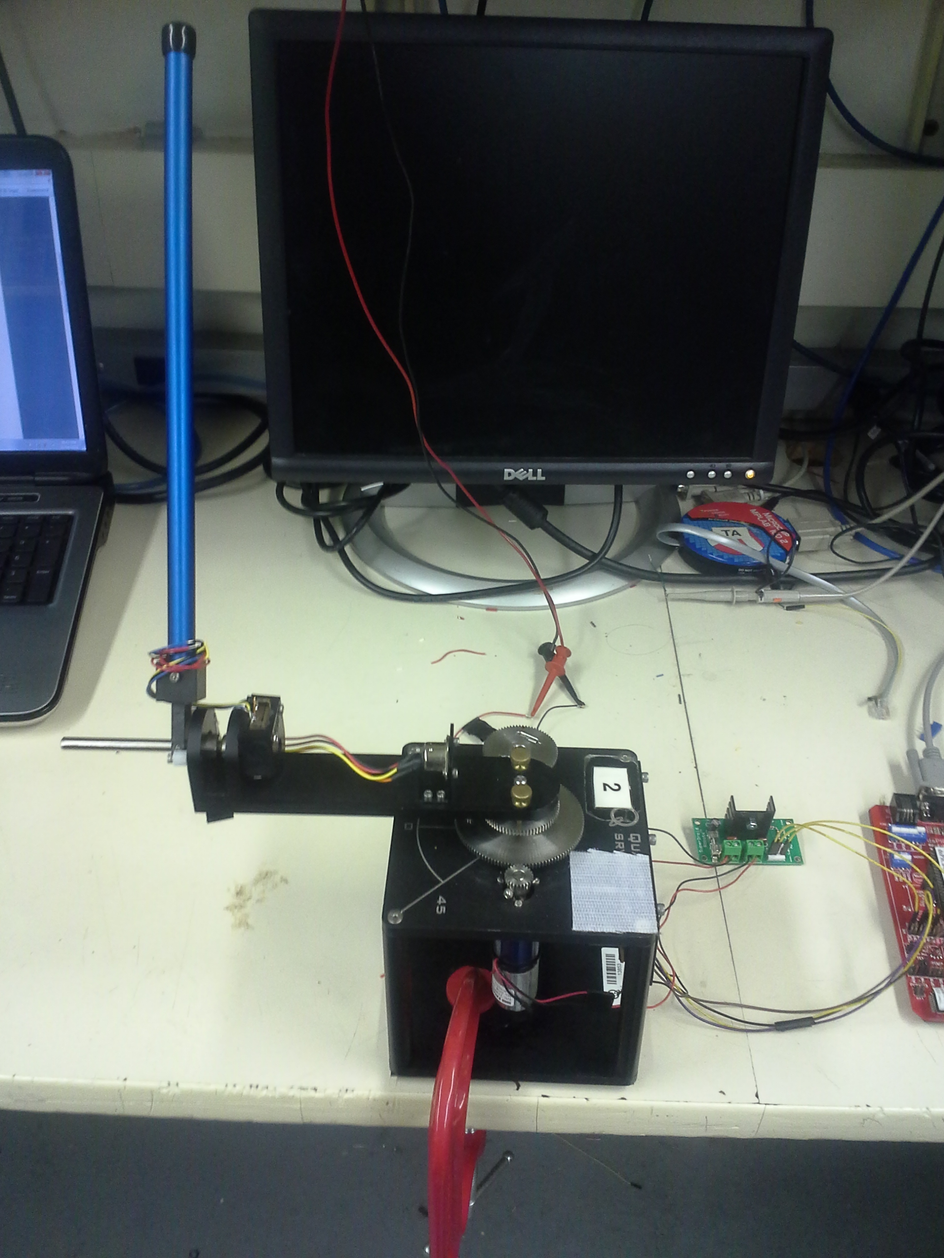
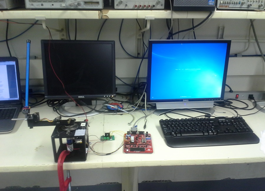
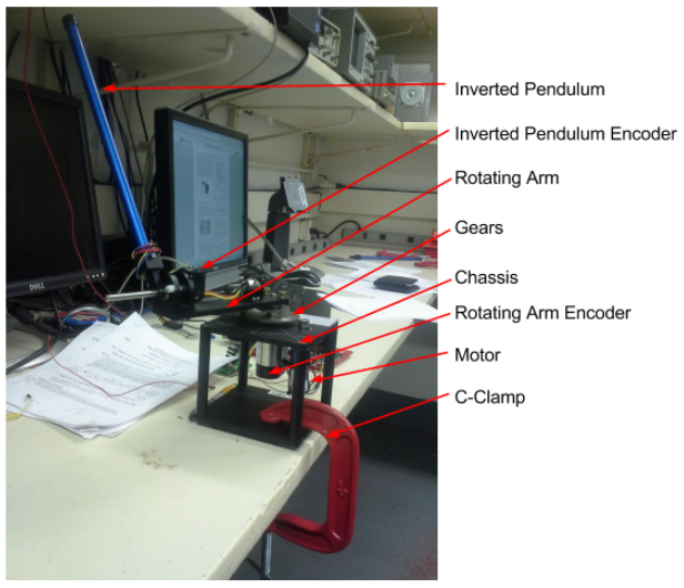
This project was a semester long project of 18-474 Embedded Control Systems course at Carnegie Mellon University. The goal of the project was to create a control system that would maintain the inverted pendulum upright and in the same position, and be robust to perturbations without becoming unstable. It was done in collaboration with Athma Narayan.
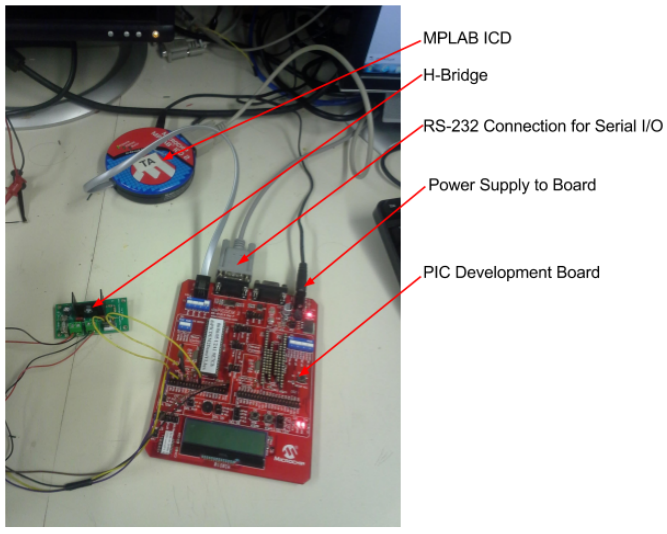
An aluminium chassis housed the electrical motor and gearbox. A quadrature encoder was attached to the output shaft of the gearbox. This gave the position the rotating arm. The inverted pendulum was attached to the end of the rotating arm. Another quadrature encoder was attached to the inverted pendulum so that the position of the arm would be known. A Microchip dsPICDEM2 development board was used to control the motor to ensure the inverted pendulum remained upright. A H-bridge allowed the direction of the motor to be reversed and the MPLAB ICD served as the interface between the development board and the computer.
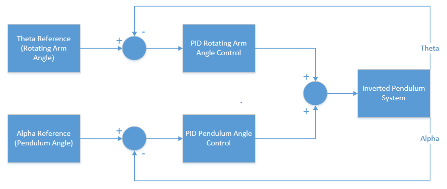
To control the pendulum, 2 parallel PID controllers were used. One was used to control the angle of the rotating arm, and the other to control the inverted pendulum itself. The control value for each of these two individual PID loops were added and the resulting control value sent to motor. First the dynamics of the system were derived and then modelled in MATLAB's Simulink environment. The controller was then coded in embedded C, put onto the controller and then the gains were tuned to get the best performance. The controller is shown below.
A GUI was created using MATLAB with the purpose of easily tuning the PID gains. The gains were set on the GUI then sent via a serial RS-232 communication interface to the microcontroller. If this were not done, each time the gains needed to be adjusted the code would have to be continuously modified and reloaded into the controller. After some tuning the controller was very successful. The pendulum balanced quite well and was very responsive to disturbances. When perturbed, the system corrected itself and returned to the desired reference position very quickly. The video below shows the pendulum in action.
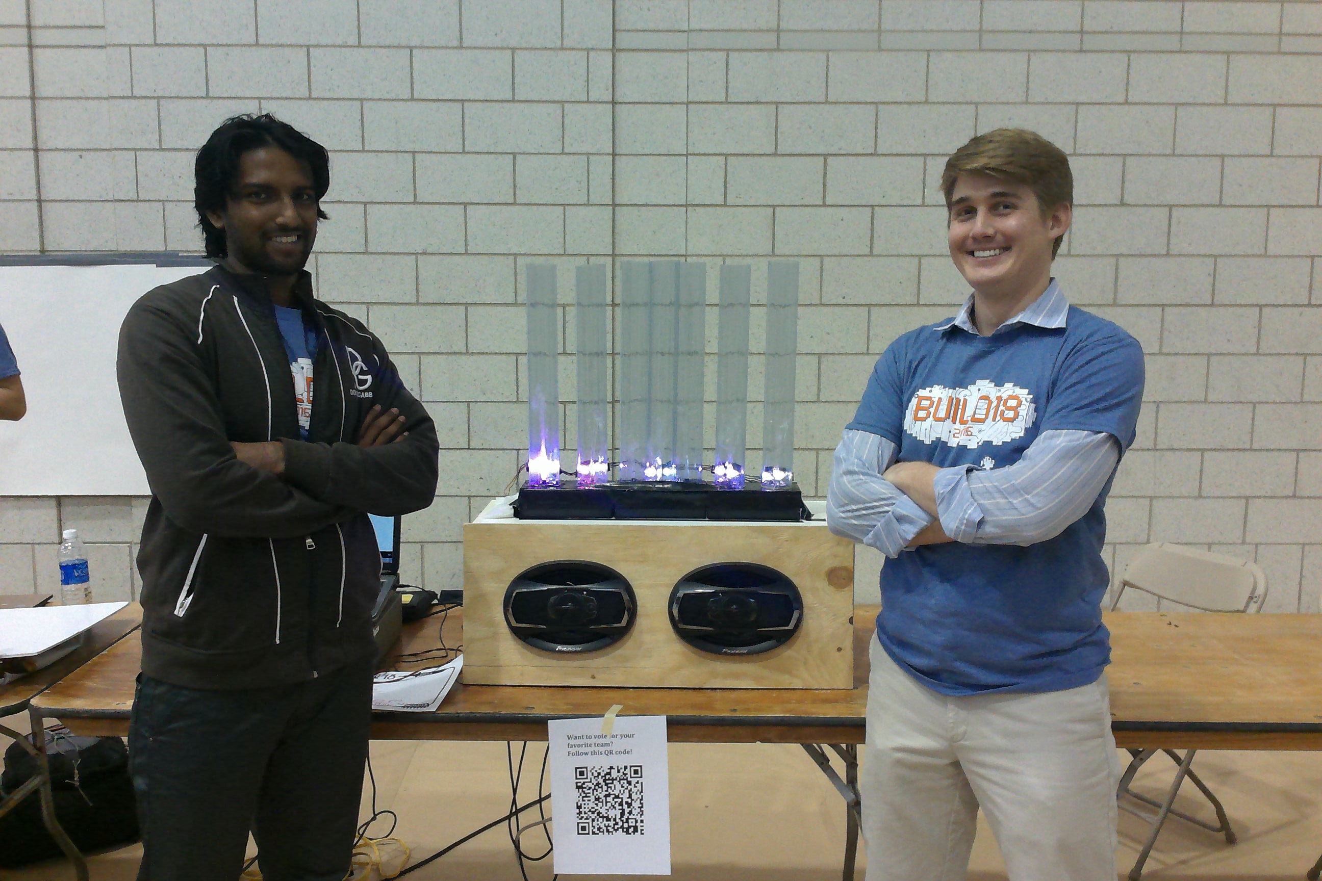
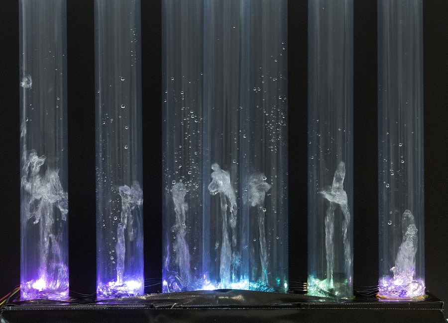
The Desktop Water Fountain Spectrum Display is an entertainment device that connects via a 3.5mm jack to any media player. The water fountain dances in the same pattern of the audio spectrum of the sound being played. It was done for the annual Build18 competition held at Carnegie Mellon University. This project won the Build18 Officer's Choice Award. It was done in collaboration with Miller Sakmar
A spectrum analyzer board outputs the amplitude of 7 frequency bands of the sound being played. An Arduino Uno takes this as an input and outputs a proportional signal to a custom designed circuit that filters and amplifies the signal which is used to control 7 waterpumps to shoot jets of water in a pattern and height equivalent to the frequency spectrum of the sound being played. A BOSS 400W amplifier boosts the sound and outputs it through a pair of Pioneer 6x9 speakers.
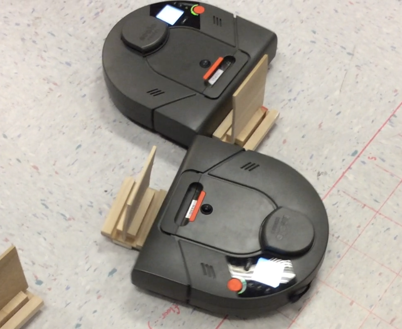
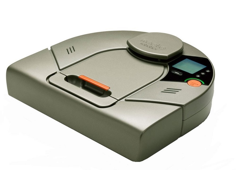
Mobile Robot Programming was a semester long course, taught by Professor Alonzo Kelly. The main aim of the course was to teach the students how to create the software for a mobile robot. The robots were Neato vacuum robots which had been retrofitted custom hardware and software such that it became a mobile forktruck. My team consisted of three members Ben Post, Jake Kligensmith and myself.
The only software provided were the base commands for controlling the motors, turning on the 2D scanning laser and communication. The robot communicated via WiFi with a laptop and programming was all done in MATLAB. Each week, additional functionality was added to the robot. It began with basic sensing the state of the robot such as distance travelled and speed which then progressed to feedback control, basic perception, state estimation and path planning. After this was completed more complicated functions were coded such as visual servoing, obstacle detection and localization.
All of this was done in preparation for the final competition where two teams' robots were pitted against each other in a race to see which robot could pick up the most number of palettes. My team programmed a smart function in our robot which centered the robot if it were off center from a palette before it picked it up. This can be seen in action in the video below. This gave our robot an edge over the other robots and we emerged victorious.
This was by far one of the best classes I took during my undergrad at Carnegie Mellon. It was a very practical class and I got to apply my theoretical robotics knowledge. Possibly even more importantly it taught me a lot of collaboration and team work skills, which is a very important asset to possess in the real world.
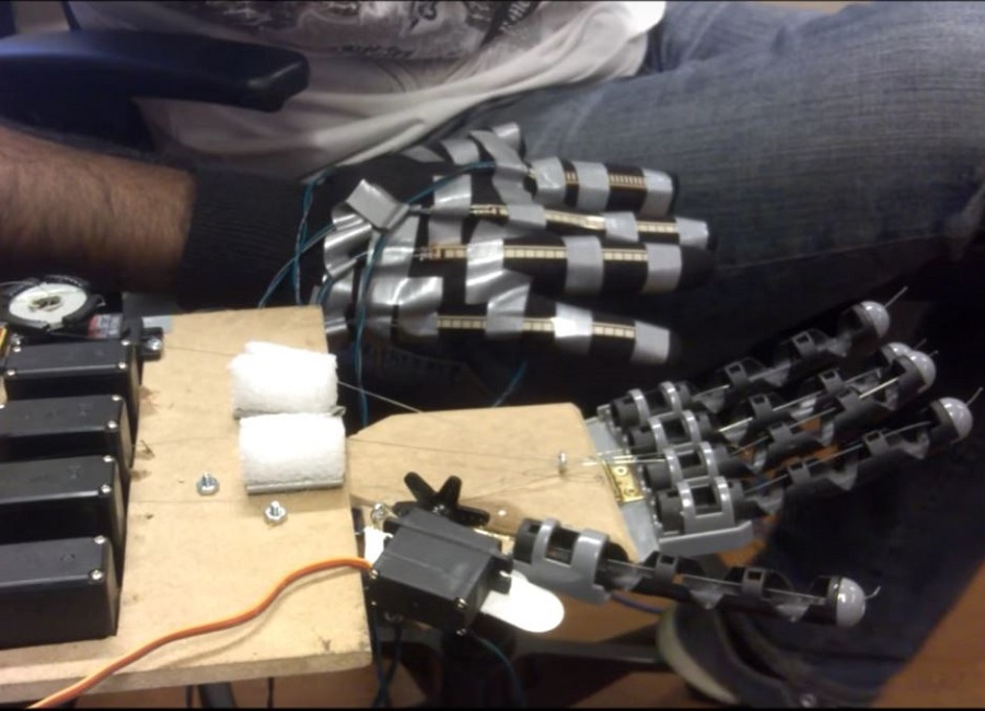
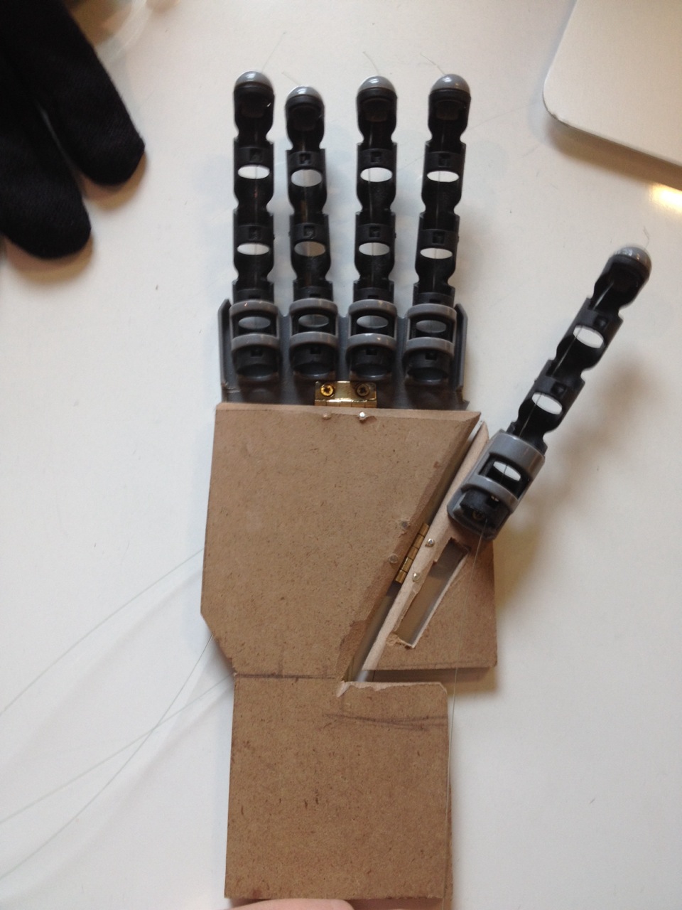
This humanoid robotic hand was final project for 16-264 Humanoids course, taught by Professor Chris Atkenson. It was done in collaboration with Miller Sakmar and Yichu Jin. The human hand is a complex device and it allows us to carry out all our daily tasks. Not only do the fingers move to grip objects, but also, the palm itself moves. About an inch from the fingers, the palm pivots, in addition to pivoting diagonally across the palm. Without this movement, objects will be more difficult to grip because the palm first wraps around and object and then the fingers secure it in place. All of the robotic hands today have finger acutation, that is, the fingers move in a way similar to human fingers. However very few robotic hands have palm actuation. Those that do are very expensive. As such, the aim of this project was to develop a humanoid robotic hand with both finger and palm actuation with only a budget of $300.
The fingers of the hand were taken from a kids grabber toy. The palm was made from particle board. The top section of the hand, with the four fingers was attached to the top of the palm with a small hinge. A slanted cut was placed along the palm and the thumb was attached to this. This entire setup was then attached to the hand via a small hinge. These mimicked the two points of actuation similar to a human hand. Fishing wire was then wound through the fingers. This can be seen below.
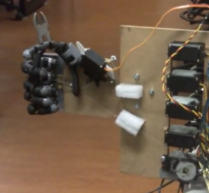
The finshing line was connected to servos. An additional smaller motor was attached to the thumb to move it. A spring was attached to the back of the actuation point at the top of palm to return it to the resting position when a force was not being applied. The following two images show the final setup.
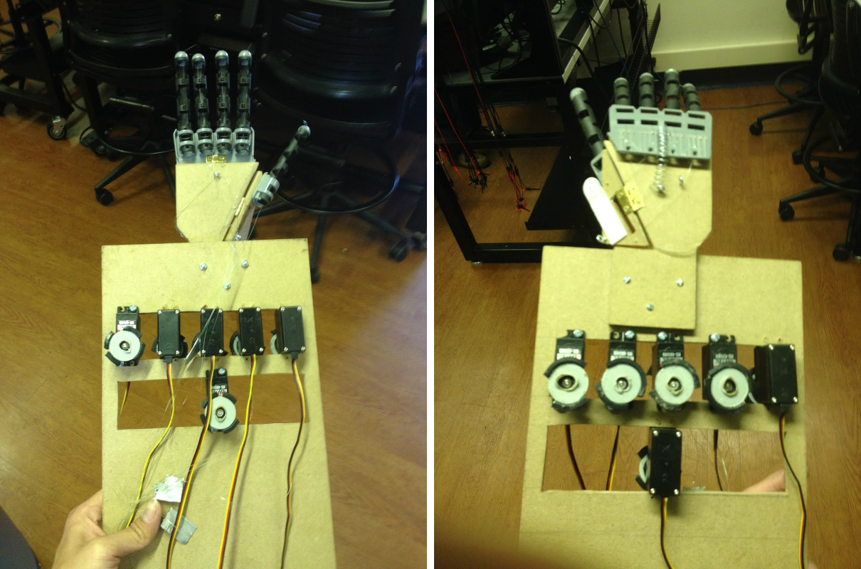
To control the hand, a glove was retrofitted with flex sensors on each of the fingers and the palm. The flex sensors are resistors which change their resistance based on how much they are bent. This data was sent to the two Arduino Unos which transformed the reading from the sensors to the appropriate angle each servo needs to turn in order to move the fingers and palm of the robot hand in a manner similar to the human hand. Below is the project video which shows the palm in action. Below the video is a link which details the design and build process of the hand.
Further details of the design and build process
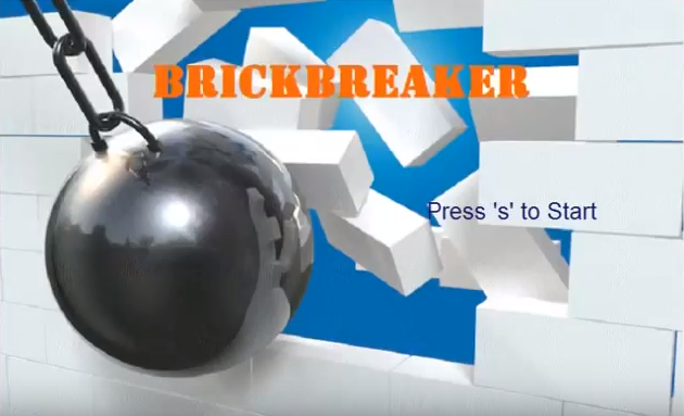
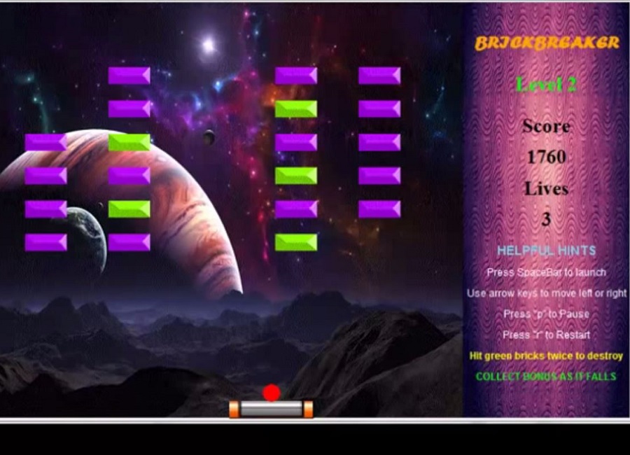
Brick Breaker was my first major programming project. It was the final project for 15-112 Intro to Programming class at Carnegie Mellon University. The game has a welcoming user interface which displays all the necessary information about the current game as well as helpful hints for the user. The player proceeds through 3 levels of gameplay, each one increasing in difficulty with more complex bricks and brick patterns. The player can collect bonuses to make gameplay more fun and interactive.
Brick Breaker was programmed in Python and made use of the tkinter module. The most complicated part of the project was programming in the physics of the moving ball. It made use of Newton's 3rd Law: Every action has an equal and opposite reaction. As such when the ball hit a brick, the ball was programmed to rebound with the same speed in the opposite direction. An example that showed how well this worked, was when the ball hit a corner of the brick, it rebounded with the same speed at the exact approach angle that it took to the corner of the brick. This models what would happen in perfect condition in reality.

FIRST Robotics has been holding robotics competitions worldwide for many years. The organization has developed a new competition called FIRST Global Robotics Challenge. This competition is geared towards bring STEM education awareness to countries where STEM education does not play a significant role. Additionally the competition aims to steer robotics in a direction to help the world. The FIRST Global Challenge is called H2O Flow and its goal is to allow teams to learn about real-world water scarcity and contamination issues. More information about the competition can be found at this link
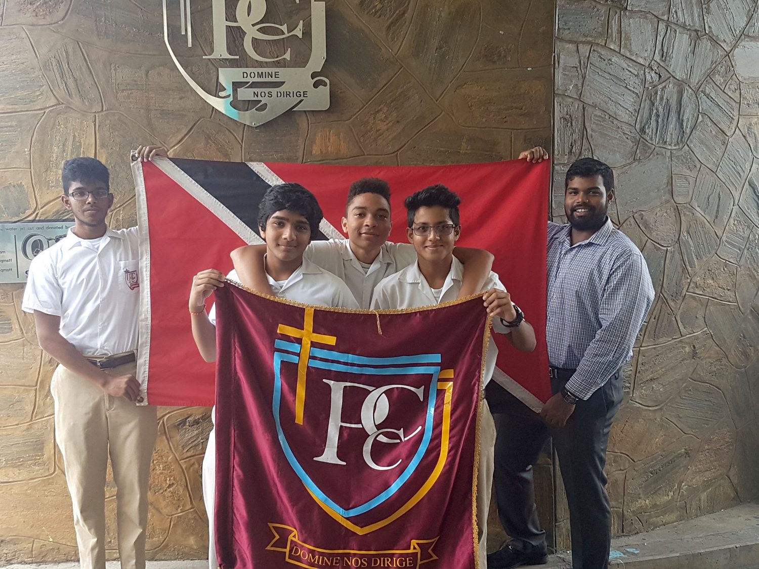
In January 2017 I was asked to join the Global STEM Corps. This was a group of volunteers tasked with mentoring nations participating in the FIRST Global Competition. When I joined, I noticed that my country, Trinidad and Tobago, was not represented. I asked the organizers of FIRST Global if Trinidad and Tobago could still join the competition and I was given permission to form a team. As such I began leading, mentoring and organizing Team Trinidad and Tobago. This is the first time to my knowledge that Trinidad and Tobago was represented on a global stage in the field of robotics. This had always been one of my dreams and it finally came to fruition.
I approached my contacts back home and formed an organizing committee mainly comprised of alumni from my high school. I then spoke with the teachers of my high school and we formed a core team of three students and a mentor who worked dilligently on building the robot. We were also able to secure sponsorship from FIRST Global, First Citizens Bank and Phoenix Park. The parents of the students were also very helpful. One parent built the mock up course for the robot, while others oversaw the team apparel, media relations and sponsorship.
I was in constant contact with the team, mentoring them through the process of building the robot. I met with them multiple times each week via Skype where we discussed issues, ideas and tactics. I also liaised with the FIRST Global organizers to ensure that all the logistics were on track for the team.
The team traveled to Washington DC from July 14-19th 2017 to partcipate in the competition. Though the competition was fierce, Team Trinidad and Tobago placed 16th out of 163 countries! This was a massive victory especially for a country which had never historically been involved in robotics especially at an international level. Personally I achieved a lifelong dream of helping inspire the next generation of roboticists.Throughout the journey I learnt important leadership, project management and communication skills. I am truly honoured and humbled to have lead the team to success.
Here are two articles from local news outlets:
The following is an interview with I gave during the competition.
Below is a video of the team being highlighted on a local news station CNC3's The Morning Brew Program.

Use this area of the page to describe your project. The icon above is part of a free icon set by Flat Icons. On their website, you can download their free set with 16 icons, or you can purchase the entire set with 146 icons for only $12!
Use this area of the page to describe your project. The icon above is part of a free icon set by Flat Icons. On their website, you can download their free set with 16 icons, or you can purchase the entire set with 146 icons for only $12!